Wednesday 2 August 2017

CLASSIFICATION OF SURVEYING - ENGINEERING GUIDE

Classification of surveying:

Definition of Surveying:
It is defined as an art to determine the relative positions of points on, above or beneath the surface of the earth, with respect to each other, by measurements of horizontal and vertical distances, angles and directions.

Classification of surveying based  on Accuracy:


1. Plane Surveying
Survey in which the mean surface of earth is regarded as plane surface and not curved as it really is, known as plane surveying. Following assumptions are made in this surveying.
  • The error introduced for a length of an arc of 18.5 km is only 0.0152m greater than the subtended chord. The difference between the sum of the angles of spherical triangle and that of plane triangle is only one.
  • Plane surveys are done for engineering projects on large scale such as factories, bridges, dams, location and construction of canals, highways, railways etc, and also for establishing boundaries.
2. Geodetic Surveying
Survey in which the shape of the earth's surface is taken into account and a higher degree of precision is exercised in linear and angular measurements is termed as geodetic surveying. Such surveys extend over large area.

Classification of surveying based  on Instrument:


1. Chain Survey 
When a plane is to be made for very small open field, the field work may consist of linear measurements only. All the measurements are done  with a chain and tape. It is recommended for plans involving the development of buildings, roads, water supply and sewerage schemes.

2. Transverse Survey
When the linear measurements are done with chain and tape and the directions or angles are measured with compass or transit theodolite respectively is called traversing survey. In traversing speed and accuracy of the field work is enhanced. A traverse survey is useful for large projects such as reservoirs and dams.

3. Tacheometry
This method of surveying in which both the horizontal and vertical distances are determined by observing a graduated staff with a transit theodolite equipped with a special telescope having stadia wires and anallatic lens. It is very useful when the direct measurements of horizontal distances are inaccessible. It is usually recommended for making contour plans of building estates, reservoirs etc.

4. Levelling
This is a method of surveying in which the relative vertical heights of the points are determined by employing a level and a graduated staff.

5. Plane tabling
It is a graphical method of surveying in which field work and plotting are done simultaneously. A clinometer is used in conjuction with plane table to plot the contours of the area and for filling in the details.

6. Triangulation
When the area to be surveyed is of considerable extent, triangulation is adopted. The entire area is divided in a network of triangles.

Classification of surveying based  on Purpose :

1. Engineering Survey
Surveys which are done to provide sufficient data for the design of engineering projects such as highways, railways, water, supply, sewage disposal, reservoirs, bridges etc. 

2. Construction Survey
It consists of topographic survey of the area, measurement of earth work, providing grade, and making measurement of the complete work till date.

3. Geological Survey
In this survey both the surface and sub surface is required to determine the location, extent and reserves of different minerals and rock types. Geoological structures like folds, faults and unconformities may help to locate the possibility of the occurance of economic minerals, oils etc.

4. Geographical Survey
Surveys conducted to provide sufficient data for preparation  of geographical maps.

5. Mine Survey
In this surveying both surface and underground are required.

6. Reconnaissance Survey
A visit is made to the site and all the relevant information is collected. It includes collection of existing maps of the area, tracing the relevant map portion over a paper, incorporating the details of the area, if missing, by conducting round survey.

Classification of surveying based  on Place


1. Land Survey
It consists of rerunning old land lines to determine their lengths and directions.

2. Topographical Survey
This is a survey conducted to obtain data to make a map indicating inequalities of land surface by measuring elevations and to locate the neutral and artificial features of the earth.

3. Cadastral Survey
This is referred to extensive urban and rural surveys made to plot the details such as boundaries of fields, houses and property lines. These are also known as public end surveys.

4. Hydrographic Survey
it deals with the survey of water bodies like streams, lakes, coastal waters, and consists in acquiring data to chart the shore lines of water bodies.

You may also like to view:

3. Error due to use of wrong scale in surveying
4. Error in computed results in surveying
5. Problems on Surveying

Sunday 21 May 2017

DESIGN OF DISTRIBUTION SYSTEM - Enginnering notes

Design of distribution system:


The following steps are involved in designing the distribution system.

1. Surveys and maps:

  • Position of road, streets, lanes, commercial locality industrial area etc.
  • Topographical map is also prepared.

2. Tentative Layout:

  • Showing position of treatment plant, distribution mains, distribution and balancing reservoirs, valves, hydrants etc.

3. Discharge in pipe lines:

  • Based on the density of population and other requirements, the pipes are designed for maximum hourly of maximum daily demand i.e, 2.7 times of average.

4. Calculation of pipe diameters:

  • Flow velocity remains n pipes between 0.6 m/sec to 3 m/sec.
  • The loss of head is calculated by William Hazen's formula ( nomogram formula) or by any other formula.

5. Computation of pressure:

  • Analysis of pressure in the distribution system.

Equivalent pipe method: 

                A complex system of pipes is replaced by a single hydraulically equivalent pipe. The equivalent pipe is one which will replace a given system of pipes with equal head loss for a given flow.

Hardy cross method:

               This is essentially a relaxation technique involving controlled trial and error. Following three laws are applicable.

  • In each separate pipe or element comprising the system there will be a relation between the head loss in the element and the quantity of water flowing through it.
  • At each junction, the algebraic sum of the quantities of water entering and leaving the junction is zero, i.e, sigma Q = 0.
  • In any closed path or circuit, the algebraic sum of head loss in the individual element is zero i.e, sigma h = 0.

Wednesday 26 October 2016

Doubly excited electromechanical system - Electrical Machines

Doubly excited electromechanical system

doubly excited magnetic system, doubly excited magnetic field system, doubly excited electro magnetic system, doubly excited electromechanical  system,
Doubly excited electromechanical system

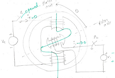
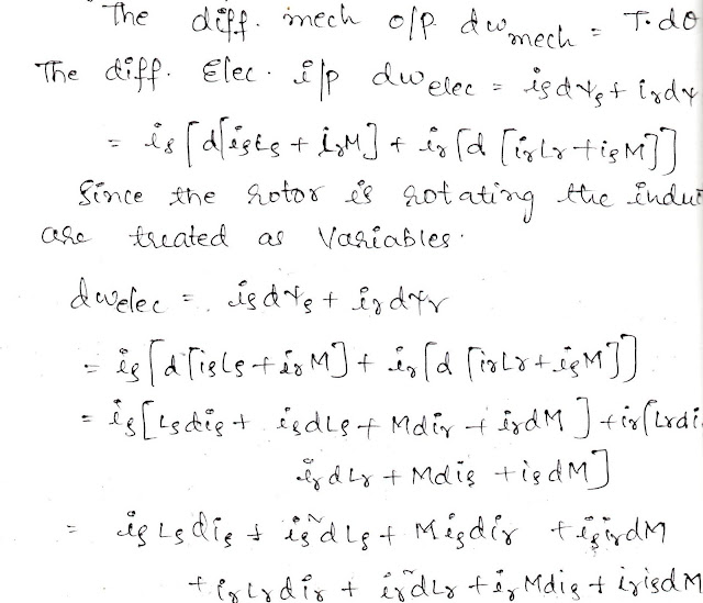
By keeping the rotor at a fixed position the switches S1 and S2 are closed. The differential electrical input to the system is equal to 


As long as the physical geometry of an electromagnetic system remains same the inductances also maintained constant.


Since the above system cannot produce any mechanical output. As the rotor is released, it starts rotating by torque T. 
Consider its rotation through a small angular displacement d(theta).


The torque developed also depends upon the angular derivatives of inductances along with stator and rotor currents.


For producing reluctance torque single excitation is sufficient but for getting mutual torque multi excitations are required.
The direction of reluctance torque cannot be reversed by reversing the excitation current whereas the mutual torque direction can be reversed either by reversing stator  current or rotor current but not both.

Singly excited electromechanical system - Electrical Machines

Singly excited electromechanical system


Singly excited electromagneticc system, Singly excited system, Singly excited magnetic system, Singly excited magnetic field system,
Singly excited electromechanical system

Excitation is the process by which energy (electrical or mechanical) is added to a system.The differential electrical input given to the system in small time dt is equal to


No electrical energy is absorbed by an electromagnetic system if its 'si' value is maintained constant. Since the above system cannot produce any mechanical output, the entire electrical input is stored in magnetic field as field energy.
  • There is no physical significance for co - energy. It is useful only for mathematical analysis.
  • Saturation is the property of a magnetic material by which its permeability decreases as the flux crosses a specified value.
 
  • The effect of airgap on electromagnetic system is 1. To linearize its magnetic characteristics i.e, no saturation. 2. It reduces the flux value for a given excitation current.

Electromechanical energy conversion - Electrical Machines

Electromechanical energy conversion process

Electro-mechanical energy conversion process is a reversible process.
Electrical machines are classified into two types based on the coupling field used.
1. Electromagnetic machines in which the coupling field is magnetic field.
2. Electrostatic machines in which coupling field is electrostatic field.

All our convention machines are electromagnetic machines due to the following advantages.
1. High energy storage capacity.
2. Safety operating conditions.

Electrostatic field is only used in electrometers to measure very high voltages.
Input = Output + losses + storage
Wim = Woe + Wlm + Wl fld+ Wle + Wsm + Ws fld 
Wl'm - Wlm - Wsm = Woe + Wle + Wl fld + Ws fld
Wmech = Welec + W fld
Above equation is the energy balance equation for generator.
Where, 
Wmech represents the net mechanical energy supplied
Welec is total electrical energy produced
Wfld is total energy absorbed by coupling field.
Welec = Wmech + Wfld
Above equation is the energy balance equation for motor.
Where,
Welec is the net electrical energy input.
Wmech is the total mechanical energy produced
Wfld is the total energy absorbed by field


Role of coupling magnetic field:

  • The coupling magnetic field in generators reacts with input mechanical energy source in terms of magnetic drag. So that the mechanical energy is absorbed and electrical energy is produced.
  • In motors, the coupling field reacts with input electrical energy source in terms of back emf so that electrical energy is absorbed and mechanical energy is produced. Hence magnetic drag and back emf are called electromechanical coupling terms.
  • In generators, as the electrical load increases magnetic drag increases.
  • In motors as the mechanical load increases the back emf decreases.
  • As long as the prime mover force is greater than magnetic drag, a machine behaves as a generator otherwise it becomes motor.
  • As long as a supply voltage is greater than back emf, the machine behaves as motor otherwise it acts as generator.

Sunday 17 July 2016

Induction type instruments - Engineering notes


Induction type instruments:

These instruments are based on the principle of induction motor.

Principle of Induction type instruments:

When a drum or disc of a non - magnetic conducting material is placed in a rotating magnetic field, eddycurrents are induced in it. The reaction between the rotating flux and the eddy current produced by it creates a torque which rotates the disc or drum. The rotating flux is produced by the current or voltage to be measured. The eddy current again is proportional to the flux.
The single phase supply is converted into two phases in the instrument, that is done by split phase or shaded pole arrangement. Accordingly induction instruments are classified as
1. Split phase type
2. Shaded pole type

1. Split phase type induction instrument:

Construction of Split phase type induction instrument:

This is also called ferraris type instrument and is shown in the fig. It consists of a laminated magnet with the pairs of poles at right angles to each other.  Coils are wound on the poles, the opposite poles being connected in series. The coils on the two pairs of poles are connected in parallel. One set of coil is connected through an inductance and another with a high resistance to create a phase difference of 90 degrees. The input to both the coils is the current to be measured. In the center of the yoke and coil is an aluminium drum. Inside the drum there is cylindrical laminated iron core to strengthen the magnetic field.

Split phase induction instrument


Working of Split phase type induction instrument:

When the instrument is connected in the circuit diagram flows through the coils. A rotating magnetic field is produced. This field induces eddy currents in the drum and a torque is produced by the reaction of magnetic field and current. This torque deflects the pointer attached to the drum. Controlling torque is produced by spring.

Deflecting torque of Split phase type induction instrument:

deflecting torque produced is given by
T  proportional   IR. IL. f cos a  sin b  / Z
For an ammeter,  T  proportional   I2. cos a. sin b  / Z
For an voltmeter,  T  proportional  V^2  cos a. sin b  / Z
Where IR  = current through resistor
IL = current through inductor
f = supply frequency
Z = impedance of eddy current path
a = phase angle between voltage and current in resistor
b = phase angle between currents in resistor and inductor

a is almost zero and R is very much larger than reactive part of eddy paths. Hence
T  proportional   I^2 . sin b  / R
Obviously  b should be as high as possible for high torque.

2. Shaded pole type induction instrument:

Construction of Shaded pole type induction instrument:

Shaded pole type instrument is as shown in the fig. A band of copper is placed in pole faces, this makes the two fluxes of shaded and unshaded portions differ in phase by 90 degrees. A metallic disc rotates between the pole faces. The damping is provided by another magnet as shown in the fig.

Shaded pole type induction instrument


Working of Shaded pole type induction instrument:

The current flowing through the exciting coil sets up flux. Eddy currents are induced in the copper band. Flux of the eddy current opposes the flux in the magnetic core and a two phase flux same as ferraris type instrument.


Permanent magnet moving coil instruments - Engineering notes


Permanent magnet moving coil instruments:

These instruments are employed either as ammeters or voltmeters and can be used for d.c work only.

Principle of  Permanent magnet moving coil instruments:

This type of instrument is based on the principle that when a current carrying conductor is placed in a magnetic field, mechanical force acts on the conductor. The coil placed in magnetic field and carrying operating current is attached to the moving system. With the movement of the coil the pointer moves over the scale.

Construction of Permanent magnet moving coil instruments:

It consists of a powerful permanent magnet with soft iron pieces and light rectangular coil of many turns of fine wire wound on aluminium former inside which is an iron core as shown in fig. The purpose of coil is to make the field uniform. The coil is mounted on the spindle and acts as the moving element. The current is led into and out of the coil by means of the to control hair springs, one above and the other below the coil. The springs also provides the controlling torque. Eddy current damping is provided by aluminium former.
Permanent magnet moving coil instrument


Working of Permanent magnet moving coil instruments:

When the instrument is connected in the circuit, operating current flows through the coil. This current coil is placed in the magnetic field produced by the permanent magnet and therefore, mechanical force acts on the coil. As the coil attached to the moving system, the pointer moves over the scale.
It maybe noted that if current direction is reversed, the torque will also be reversed since the direction of the field of permanent magnet is same. Hence, the pointer will move in the opposite direction, i.e it will go on the wrong side of zero. In other words, these instruments work only when current in the circuit is passed in a definite direction i.e. for d.c circuit only.
It is worthwhile to mention here that such instruments are called permanent magnet moving coil instruments because a coil moves in the field of a permanent magnet.

Deflecting torque of Permanent magnet moving coil instruments:

When current is passed through the coil, a deflection torque is produced due to the reaction between permanent magnetic field and the magnetic field of the coil as shown in the fig.
Let B = flux density in the air gap between the magnetic poles and iron core.
l = active length of the coil side in meters.
N = number of turns of coil.
If a current of i amperes flows in the coil in the direction shown, then force F acting on each coil side is given by
F = BI / N newtons
Td = Force * perpendicular distance
= F * 2r newton - meters
where r is the distance of coil side from the axis of rotation in meters
Td = NBIl * 2r newton - meters
If A ( = l * 2r) is the surface area of the coil, then
Td = NBIA newton - meters
Deflection torque = Ampere turns on coil (NI) * Area of coil (A) * flux density (B)
Td  proportional  I
Since the control by springs, therefore controlling torque is proportional to the angle of deflection i.e
Tc  proportional  I
The pointer will come to rest at a position when,
Td = Tc
Deflection  proportional  I

Thus, the deflection is directly proportional to the operating current. Therefore, such instruments have uniform scale.

Advantages of Permanent magnet moving coil instruments:

1. uniform scale.
2. Very effective  eddy current damping
3. Power consumption is low.
4. No hysteresis loss
5. As working field is very strong, therefore, such instruments are not affected stray fields.
6. Such instruments require small operating current.
7. Very accurate and reliable.

Disadvantages of Permanent magnet moving coil instruments:

1. Such instruments cannot be used for a.c measurements.
2. Costlier as compared to moving iron instruments.
3. Some errors are caused due to the ageing of control springs and the permanent magnet.