Showing posts with label Choppers. Show all posts

Friday, 8 July 2016

Voltage commutated chopper - Engineering notes

Voltage Commutated Chopper


Voltage Commutated Chopper circuit diagram

  • Similar to step down chopper.
  • T1 = Main thyristor, TA = Auxiliary thyristor, L,C = commutating components, Rc = charging resistor
  • Assume output current is constant.
  • Close the switch, initially capacitor short circuited, after 4 - 5 time constants, Vc = Vs.
  • At t = 0, T1 is on, load is connected across the supply Vo = Vs.
  • Tank circuit starts conduction ( diode forward bias).
  • After conduction polarities across capacitor are changed.
  • D is reverse biased polarities across capacitor are changed.
  • Upto t2 we completed now we have to turn off the main thyristor.

  • Make TA on, T1 to be off (applying reverse voltage).
  • To make the conduction continues use free wheeling diode.
  • In order to make the output  continuous, the existing path will be changed as Vs, C, TA and the load.
  • Voltage across the capacitor changes.
  • Now make the voltage across capacitor > Vs.
  • Free wheeling diode conducts, output voltage becomes zero.
  • To start next cycle, no need to close switch 's'.
  • A reverse voltage is applied across conducting SCR due to which current through SCR becomes zero and it is getting off. Hence it is called voltage commutation.
  • Other name of this is impulse commutation. It is because a high reverse voltage will turn off the SCR.

Limitations of voltage commutated chopper:

  1. A starting circuit is required.
  2. load voltage at once rises to 2Vs at the instant commutation of main SCR is initiated.
  3. It can't work at no load. It is because at no load, capacitor would not get charged frm -Vs to Vs when auxiliary SCR is triggered for commutating the main SCr.
  4. Main thyristor is required to carry current more than load current. So, it is to be over rated.
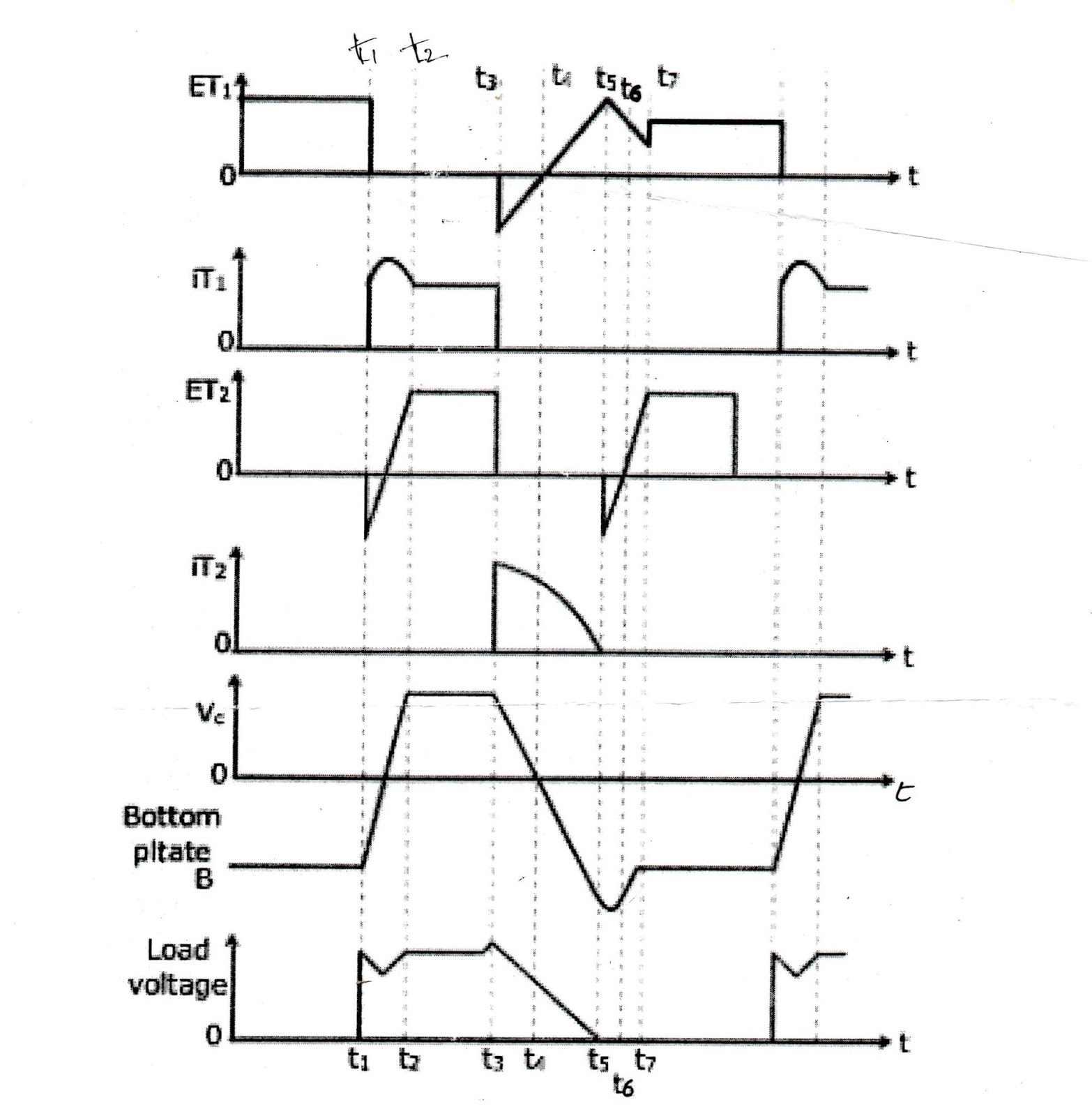
Voltage Commutated Chopper Waveform

  • The values of commutating components C and L can be obtained.
  • The values depend upon turn off time of main thyristor T1. during tc capacitor voltage changes from -Vs to zero linearly.
ic = C dV / dt  for a constant load current Io.
Io = C . Vs / tc
C = Io . tc / Vs
  • The commutation circuit turn off time tc must be greater than thyristor turn off time.
  • Load current should not be too large.

Thursday, 7 July 2016

Current Commutated chopper - Engineering notes

Current Commutated Chopper:


Current commutated chopper

  • Capacitor is charged to Vs, main thyristor T1 is fired at t = 0. So that load voltage Vo = Vs.
  • At t = t1, auxiliary thyristor is turned on to commutate main thyristor.
  • With turning on of TA, an oscillatory current ic is set up in the circuit.
  • At t2, Vc = - Vs and ic tends to reverse in the auxiliary thyristor TA, it gets naturally commutated.
  • As TA is reverse biased and turned off at t2. Oscillatory  current ic begins to flow through C, L, D2 and T1.
  • At t3 ic rises to io so that iT1 = 0. As a result main SCR T1 is turned off at t3. Since oscillating current through T1 turns it off it is called current commutated chopper.
  • After t3 ic supplies load current io and the excess current. iD1 = ic - Io is conducted through diode D1.
  • Afetr t4, a constant current equal to Io flows through Vs, C, L, D2 and load.
  • Capacitor c is charged linearly to source voltage Vs at t5, so during time ( t5 - t4 ) ic = Io.
  • In this commutation an opposite current pulse will be injected through SCR. As a result currents decreases and finally comes to zero if both the currents would be equal and opposite.
  • Anti parallel diode is useful to apply the reverse voltage after current through SCR becomes to zero. The value of reverse voltage is low. So 
  1. Turn off time increases.
  2. Turn off power loss increases.
  • Jones chopper employes the principle of voltage commutation.
  • Morgan's chopper based on the principle of current commutation.
Current and Voltage waveforms for current commutated chopper

Four Quadrant chopper / Type E chopper

Four Quadrant chopper or Type E chopper:

First Quadrant:


four quadrant chopper / Type E chopper circuit diagram
  • For this operation CH4 is kept on, CH3 is kept off and CH1 is operated.
  • With CH1, CH4 on, load voltage Vo = Vs and load current io begins to flow.
  • When CH1 is turned off, positive current free wheels through CH4, D2.

Second Quadrant: 

  • Here CH2 is operated and CH1, CH3 and CH4 are kept off.
  • With CH2 on, reverse current flows through L, CH2, D4 and E. Inductor L stores energy during CH2 is on. When CH2 is turned off, current is fed back to source through diodes D1, D4. Note that here ( E + L. di /dt) is more than the source voltage Vs.

Third Quadrant:

  •  For this operation, CH1 is kept off, CH2 is kept on and CH3 is operated. Polarity of load emf E must be reversed for this quadrant working.
  • CH3 is on, load gets connected to source Vs so that both Vo, io are negative leading to third quadrant operation.
  • When CH3 is off, negative current freewheels through CH2, D4.

Fourth Quadrant:

  • Here CH4 is operation and other are kept off. Load emf E has its polarity as in 3rd quadrant. With CH4 on, positive current flows through CH4, D2, L and E. Inductor L stores energy during the time CH4 is on.
  • When Ch4 is turned off, current is fed back to source through diodes D2, D3. Here load voltage is negative, but load current is positive. All power is fed back from load to source.

Step Up Down Choppers - Engineering Notes


A chopper is a static circuit that converts fixed dc input voltage to a variable dc output voltage directly. As choppers involve one stage conversion, these are more efficient.

Step Up / Step down Chopper

Step Up Down chopper Circuit diagram


  • When chopper is ON, current flows from source Vs to CH, L and back to V.
 
Step Up down waveform

  • Energy stored in inductor during Ton, Win = Vs. Ton (I1 + I2 ) / 2.
  • When chopper is OFF, inductor current tends to decrease by KVL VL - Vo = 0.
 

VL = Vo
Woff = Vo . Toff (I1 + I2) / 2
  • Inductor stored energy now discharges through the path, load, diode D and L during the time chopper is off.
  • Assuming the system to be lossless, the energy balance equation 
Win = Woff
Vs .Ton = Vo . Toff
Vo = Vs . ( duty cycle / 1 - duty cycle)
  • for step down chopper, Vo = duty cycle * Vs
  • for step up chopper,  Vo = ( 1/ 1 - duty cycle) Vs
  • for step up / down chopper, Vo = Vs . ( duty cycle / 1 - duty cycle)
  • For 0 < duty cycle < 0.5, circuit works as step down chopper.
  • For 0.5 < duty cycle < 1, it operates as a step - up chopper.

Wednesday, 6 July 2016

Step Down Chopper - Engineering Notes

Chopper is a static circuit that converts fixed dc input voltage to  a variable dc output voltage directly.
 

Step Down Chopper:

  • During the period Ton, chopper is on and load voltage is equal to source voltage Vs. During the interval Toff, chopper is off, load current flows through the free wheeling diode FD. As a result, load terminals are short circuited by FD and load voltage is therefore zero during Toff.
Step Down Chopper
  • During turn on Ton, load current rises where as during turn off Toff  load current decays. 
 
Step Down Chopper waveform
  • Average load voltage Vo is given by  
 Vo = Ton . Vs / (Ton  + Toff)
                               = Ton . Vs / T = duty cycle * Vs
 
Vo = duty cycle * Vs
where Ton = on - time; Toff = off - time
T = Ton + Toff = chopping period and 
Duty cycle = Ton / T 

  •  Thus load voltage can be controlled by varying duty cycle.
Vo   = f . Ton . Vs
where f = 1 / T = chopping frequency
  • Variation of  Ton means adjustment of pulse width, as such this scheme is also called pulse width modulation scheme.
  • Average output current, 
Io = Vo / R = duty cycle * V / R

Saturday, 11 June 2016

Morgan Chopper - Engineering Notes


Morgan Chopper :


Circuit diagram of Morgan Chopper

  • The circuit diagram is as shown in figure.
  • This circuit has only one thyristor.
  • The special feature of this circuit is the saturable reactor (SR).
  • The commutation circuit is formed by the capacitor, saturable reactor SR and the diode D1.
  • Assume  that the exciting current of the saturable reactor is negligibly small.
  • Load current is assumed to be constant to simplify the analysis of the chopper.

About Saturable  Reactor:

  • It is a special type of inductor in which the magnetic core is deliberately saturated by some external means.
  • With the change in the direction of current, the saturation polarity is also changed i.e, if for one direction of current the saturable  reactor is in positive saturation then for another direction of current  it will be in negative saturation. This is obvious from the hysteresis loop of a magnetic material.
  • For any inductor, it has very high inductance during unsaturated condition and has very low inductance during saturated condition.

Circuit Operation of Morgan Chopper :

Morgan chopper waveforms

  • Before turning on the thyristor T1, load is flowing through free wheeling diode. In this period capacitor voltage is Vs. Capacitor is charged through this voltage by the source through Vs - C - SR - load - Vs. 
  • During this period saturable reactor is placed in positive saturation position and for current passing through SR from left to right, SR will be in positive saturation.
  • When T1 is turned on, load current shifts from free wheeling diode to the main SCR. In this period the capacitor voltage will appear across SR. With this applied voltage, SR will drive itself into negative saturation from the positive saturation.
  • When SR is negative saturated its inductance will fall and discharge of capacitor will occur in a very short time.
  • Now the capacitor is negatively charged and this voltage is applied across SR. With this applied voltage SR drive into positive saturation from the negative saturation.
  • Exciting current of SR is very small, so capacitor holds its voltage till SR drives into saturation.
  • When SR is saturated (positive saturation) its inductance will fall and discharge of capacitor will occur in a very short time during the negative current flow through SCR, SCR will turn off. After turn off of SCR, the discharge current flows through the diode D1.
  • After turn off of SCR the load current shifts again to free wheeling diode.
  • For the next cycle same sequence of steps are repeated.

Jones chopper - Engineering notes


Jones Chopper : 

Jones Chopper Circuit diagram
  • The circuit diagram of Jones chopper is as shown in the figure.
  • Let us assume that the given polarities in the diagram are positive.
  • T1 is the main thyristor  and T2 is the auxiliary thyristor.
  • This circuit is an example of voltage commutation. The special feature of this circuit is the tapped auto transformer.
  • Load current flows through some portion of auto transformer winding. The two portions of the auto transformer winding are closely coupled.
  • Because of this auto transformer, commutating capacitor gets sufficient energy to turn off  the main thyristor.
  • Load current is assumed constant to simplify the analysis of this chopper.

Circuit Operation of Jones Chopper:

Jones Chopper waveform
  • Before turning on the main thyristor T1, load is flowing through free wheeling diode. In this period capacitor voltage is -Vs.
  • When main thyristor turn on load current shifts from free wheeling diode to the main SCR. In this period an oscillating circuit is formed with Lr and C.
  • This oscillating current flows through C - T1 - L2 - D1 - C. In this period capacitor gets charged in the reverse direction. By the end of this period Vc = +Vs
  • When auxiliary thyristor T2 is turned on, the capacitor will appear across T1 as reverse voltage and T1 will get turn off . Now the load current flows through Vs - C - T2 - L1 - load - Vs.
  • When capacitor voltage becomes -Vs, free wheeling diode will get turn on and the load current shifted to free wheeling diode.
  • But the inductor L1 has some amount of stored energy. Inductor stored this energy when load current is flowing through it.
  • When load current shifts to free wheeling diode, the energy stored in inductor L1 is transferred to capacitor through L2 ( since it is an auto transformer).
  • Because of this capacitor voltage rises initially and settles down to -Vs.
  • For the next cycle same sequence of steps are repeated.